Comparison of Voltage Drive and Current Drive of a Woofer – Effect on Sound Quality
Purpose of the document:
The achievable sound quality in terms of linearity and harmonic distortion is heavily depending on the way the chassis is driven. It is demonstrated, that Current Drive is by a factor of 10 superior to the usual Voltage Drive of a chassis.
What is it about?
Voltage Drive (VD) is the usual operation condition of a chassis.
The driving impedance of the power amplifier is (ideally) zero.
The voltage at the voice coil is controlled (voltage feedback) to be constant over the frequency.
The current through the voice coil results from the difference between terminal voltage of the chassis and the velocity induced voltage divided by the voice coil impedance.
Current Drive (CD) is a more suited operation condition for a chassis.
The driving impedance of the power amplifier is (ideally) infinite.
The current through the voice coil is controlled (current feedback) to be constant over the frequency.
The voltage at the voice coil cannot generate any current through the voice coil, as the driving impedance is infinite and acts as open loop.
The main difference between the two operation conditions:
With CD the velocity induced voltage has no effect, but with VD it has one.
The following measurements show the significant difference between CD and VD on the frequency response of a chassis in an enclosure and on the frequency dependent harmonic distortions.
The used chassis for the following measurements is a SEAS L22RNX/P in an 18 liter enclosure.
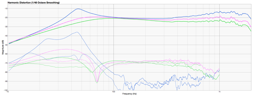
Comparison of Current Drive and Voltage Drive
Blue: Sound pressure level (SPL) frequency response from 10 Hz to 2 kHz with Current Drive (CD), green with Voltage Drive (VD).
Lower dashed curves: Third harmonics, Lower solid curves: Second harmonics.
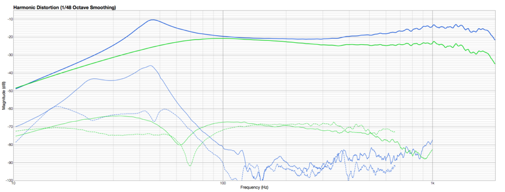
VD reaches about -50 dB harmonic distortions, CD reaches about -70 dB harmonic distortions. Current Drive is a factor 10 better above the resonance frequency (45 Hz) at comparable SPL.
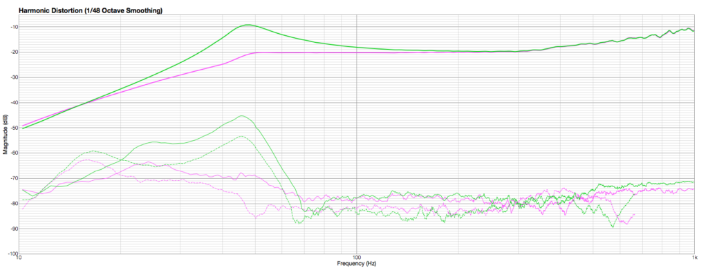
In today’s world the resonance peak (represents Qms) resulting from CD can easily be equalized – that can be done very simply in the electronics of the power amplifier. The example below shows the result of an equalizing parametric filter (f0 = 46 Hz, G = -13 dB, Q = 1.4) that exactly compensates the resonance of the chassis with current drive.
Magenta shows the SPL frequency response after Pole-Zero-Compensation of the transfer function resulting in an absolutely flat frequency response. The pole (resonance of the chassis) is compensated by an (electronically realized) Zero of the transfer function at the same frequency and with the same quality factor.
What is behind this significant difference in sound quality?
Measurement of the SPL (blue) with Current Drive and the resulting voltage (red) of the voice coil.
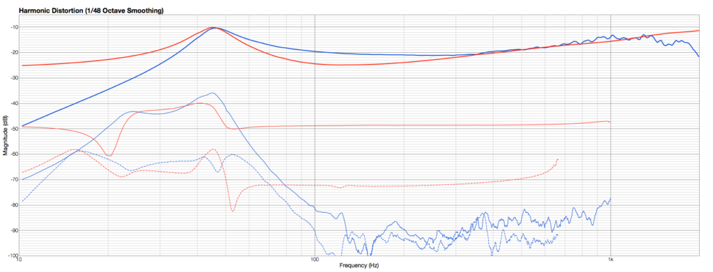
Obviously, the generation of the back induced voltage is a rather non-linear effect (it generates about -25 dB harmonic distortion) for the second harmonics. This indicates an axisymmetric nonlinearity (disturbed even function), while the third harmonics is a factor 10 lower indicating a cleaner point symmetrical odd function.
This is not surprising, when one has in mind e.g. the Eddie Currents mainly in the pole piece, the variation of the magnetic field by the voice coil current and by the voice coil position in addition to the nonlinear compliance of the chassis.
Under CD the velocitiy induced voltage has, however, no effect on the current through the voice coil. Such the visible non-linearity of the voice coil voltage simply doesn’t matter.
That is the main reason, why CD is superior to VD.
Measurement of the SPL (green) with VD and the resulting current (violet) through the voice coil.
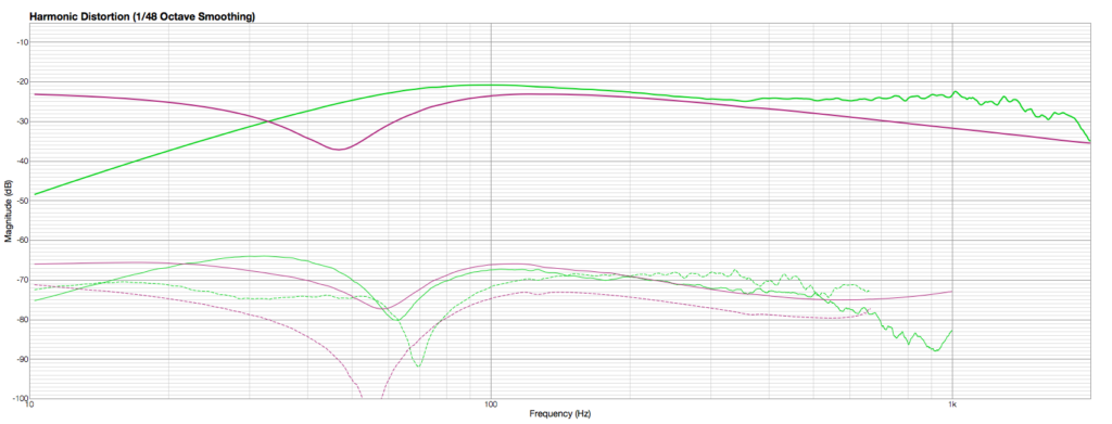
The current shows now the characteristic dip at the resonance frequency of the chassis, which is not any more visible in the SPL frequency response (over damped, Q < 1).
The resulting voltage at the voice coil shows about -50 dB harmonic distortions as it is the case for the SPL.
The chassis is now on one hand electrically damped, but on the other hand the harmonic distortions of the voltage at voice coil are now equally reflected in the SPL frequency response. Classical operation condition, but not a good one.
For the operation of woofers, one has tree alternatives to the classical VD:
- Use a small air volume (Qts << 1) and CD (AC-PAZ75).
Air is a linear spring and linearizes the chassis compliance. Equalize electronically the frequency response e.g. via a Pole Zero Compensation. That works well, extends the frequency response significantly towards lower frequencies. Good quality (about 3% harmonic distortions) with little electronic effort. - Use an adapted driving impedance (adapted to the chassis in its enclosure, AC-PAZ75). The impedance is between CD and VD. The adapted impedance is adjusted such, that the chassis in its enclosure reaches the required Q-factor (around 0.9). See frequency response chart below
- Use Motion Control of the voice coil. Best possible quality (about 0.1% harmonic distortions and a lower cut-off frequency at wish (e.g. 15 Hz).
The required sensor has its price and needs mounting into the voice coil. The price of a MFB power amplifier (AC-PAR75) is not much different from a current control amplifier AC-PAZ75 as used in option 1.
Frequency Response with adapted impedance
Magenta represents the operation of the chassis with adapted impedance. This impedance is adjustable (AC-PAZ75) and delivers the required quality factor. Obviously, the frequency response is extended towards lower frequencies compared to VD, however, the harmonic distortions are about the same as for VD.
Conclusion
A significant better operation method for a chassis is CD, delivering about a factor 10 better linearity or lower harmonic distortions compared to VD. The price in case of a woofer with Qts > 1 is a simple equalizer before or inside the power amplifier.
Tweeters are usually acoustically well damped (Qts = 1) and do not need any equalizing with CD.
The second-best option is using the adapted Impedance, which makes any frequency shaping obsolete and allows to electronically adjust the total quality factor of the box at wish.
For High-End purpose nothing can compete with motion feedback.
All non-linearities of the chassis are reduced to about 0.1% and the original resonance frequency is not any more present. This allows lower cut-off frequency at wish. AudioChiemgau uses as default value 15 Hz (-3 dB).
AudioChiemgau offers Power amplifiers for all three driving modes as well as the motion feedback sensors to be mounted into the voice coil.
All measurments are done with our ModeCompensator