Mode-Compensator for Precise Measurement of the Sound Pressure Frequency Response in Presence of Room Modes
Purpose of the Equipment
This equipment is foreseen for the precise and high-resolution Room-Mode-Free Measurement of the Frequency Response and harmonic distortions of Loudspeakers in a standard laboratory environment.
It is intended to be used in combination with a measurement equipment as e.g., a computer with audio interface and an appropriate evaluation software.
Introduction
The usual method of measuring the frequency response and distortions of the Sound pressure level (SPL) of a loudspeaker chassis (device under test, DUT) uses time gating. The time window (time gate) in which the sound pressure is recorded is set such, that the reflections of the sound from the walls, which arrive after their distance depending traveling time and resulting room modes (room resonances) are excluded from the measurement.
The time domain measurement is then transformed into the frequency domain by an appropriate evaluation software in order to get the frequency response of the SPL. Because of the transformation the time window determines the achievable frequency resolution of the measurement. Time window length and frequency resolution are reciprocal parameters.
In most laboratories the distance from the DUT to the next hard boundaries (walls. ceiling, floor) is below 2 meters. As the sound travels 343 Meters per Second, the first reflection from the wall arrives after about 11 Milliseconds. A corresponding time window set to 10 Milliseconds results in a frequency resolution of 100 Hz.
It becomes clear from the above example that frequency measurements below 1 kHz are not possible with acceptable frequency resolution and accuracy.
The AudioChiemgau ModeCompensator overcomes that problem and enables the measurement of the SPL and the harmonic distortions with very high frequency resolution and accuracy down to 10 Hz.
Its basic principle eliminates the reflections and room modes resulting from hard boundaries from the time domain measurement. For this purpose, two microphones are used to distinguish the direct sound of the DUT from the unwanted room reflections, especially room resonances, but also ambient noise.
Such the time window of the evaluation software can be set according to the desired frequency resolution of the SPL frequency measurement. For low frequency measurements a time window of 10 Seconds is used in order to get 0.1 Hz frequency resolution down to 10 Hz (frequency limit of the used MEMS microphones).
Theory of Operation
AudioChiemgau offers a simple technology solving the discussed measurement problem:
The loudspeaker is measured in the near field (5 .. 10 cm between membrane and measurement microphone) and simultaneously the room modes are measured with a second microphone (5 cm distance between the two microphones).
Both microphones record the direct sound pressure from the chassis and the room modes according to the inverse proportional law.
The SPLs of the direct sound are significantly different for both microphones, as the relative distances from the source (loudspeaker membrane) are significantly (e.g. factor two) different .
The SPLs of the modes and the noise floor in the room are practically equal at both microphones, as the sound waves traveled already a comparable large distance before arriving at the microphones.
The Mode-Compensator uses this physical relationship and derives in real time a mode free SPL signal from the loudspeaker under test.
Package Content and Price
The ModeCompensator is available from AudioChiemgau.
The selling price of
per unit comprises the following equipment:
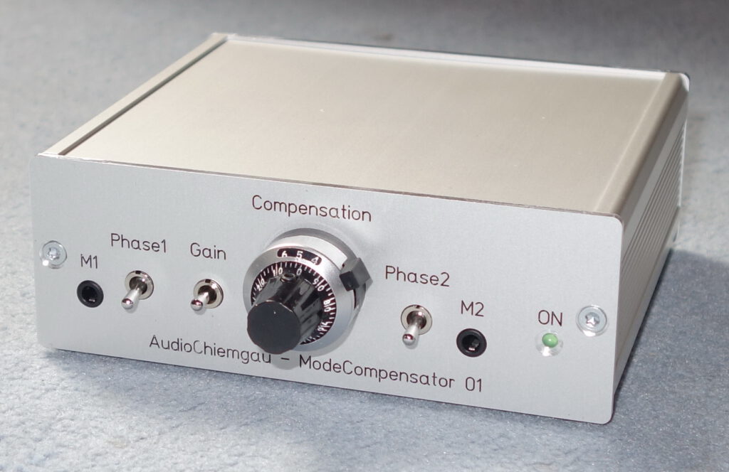
- ModeCompensator control unit
- Two calibrated MEMS measurement microphones with cables (1.5 m)
- Wall-plug power supply (100 VAC … 240 VAC 50/60 Hz)
- Operation Instructions (english)
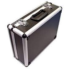
- Transportation and protection case (250 mm x 150 mm x 320 mm)
The price for ModeCompensator, purchased from AudioChiemgau (Germany) and delivered to a destination located in the European Union (EU), includes VAT and duties.
User guide for ModeCompensator 01
Necessary supporting Equipment
The following equipment is required for frequency response and harmonic distortion measurements:
- Personal Computer
Examples: Apple Mac Book, iMac or Windows based Computer - External or high quality internal audio interface
Examples: USB audio interface Focusrite Scarlett 2i2 or Clarett 2pre USB - Evaluation software
Examples: FuzzMeasure (Mac OS) or EQ Wizard (Windows, MacOS and Linux)
There are many more commercial evaluation software alternatives for Apple or Windows computers on the market.
Trademarks: Microsoft and Windows, as well as Apple and Focusrite are registered trademarks. All other trademarks are property of their respective holders.
Example for A SPL frequency Response
The measurement shows the SPL frequency responses of a chassis in an closed box with ± 0.1 dB SPL accuracy and 0.1 Hz frequency resolution measured in a standard laboratory.
Sweep time 10 Seconds and time gate 10 Seconds corresponding to a frequency resolution of 0.1 Hz.
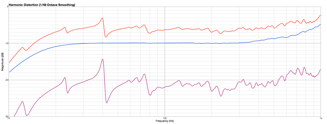
Red is the measured SPL of the “direct” microphone in 5 cm distance to the membrane.
This is what one usually measures in a standard laboratory for a closed box. Open Baffles excite by far less room modes than a closed box.
Violet is the measured SPL of the “mode” microphone in 10 cm distance to the chassis.
Blue is the mode free SPL frequency response derived from the above two measurements using the ModeCompensator.
Remarks:
- The visible low-end frequency response is resulting from the loudspeaker under test (-3 dB @ 16 Hz).
- The distances between the two MEMS microphones with respect to the DUT need to be accurately adjusted in order to achieve a flat frequency response of the ModeCompensator ( ± 0.1 dB) up to 1 kHz.
- It is recommended to use the ModeCompensator for frequencies below 1 kHz, as the equalization of the frequency response of the ModeCompensator is accurate up to 1 kHz. Above 1 kHz appropriate short time gating can be used in a standard laboratory environment by using one of the two direct outputs of the ModeCompensator.
- The above Frequency plot is generated with a Clarett 2pre and FUZZMeasure.
Calibrated frequency response of the Microphones
The SPL frequency responses of the two MEMS microphones are calibrated relatively to each other and with respect to a Bruel&Kjaer reference microphone. Deviations are typically below ± 0.1 dB between 10 Hz and 1 kHz.
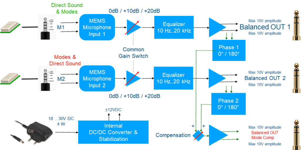
Block diagram and I/O Specification
The following figure shows a block diagram and the input/output specification of the ModeCompensator
Additional information is provided in an Application Note AC-AN-010: Precise Measurement of the Sound Pressure Frequency Response and the Harmonic Distortions of Loudspeakers in a Standard Laboratory Environment (english only)